- All Products
- Frontier Hydrant Test Kit Only (BAT)

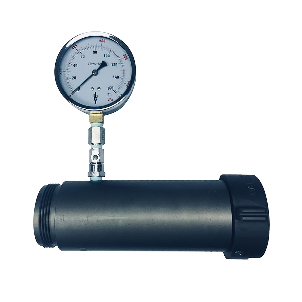
Frontier Hydrant Test Kit Only (BAT)
Case not included

Hand Tools
Frontier Hydrant Test Kit (BAT) – Precision Flow Testing for Hydrant Performance 🚰
The Frontier Hydrant Test Kit is designed for accurate, efficient hydrant flow testing using the pitot method—where water flow is determined by measuring the stream’s velocity (pressure) through a known nozzle tip diameter. The included pitot measures flowing water pressure at the test point, displayed in PSI on a large, easy-to-read 4" gauge with ±1% full-scale accuracy. Flow charts are provided for precise calculations.
Key Features:
- Pitot Method Accuracy: Provides direct, reliable readings of stream velocity pressure, allowing users to determine hydrant flow rates by referencing included charts and formulas[1][3][4].
- Kit Includes: 1.50" (38mm) nozzle tip (other sizes available), 4" 0–160 PSI swiveling/removable gauge, all hard-coated anodized aluminum parts, and flow charts for quick reference.
- Practical Range: Measures flows from 151–1,851 GPM at 10–140 PSI, depending on tip size and water pressure.
- Consistent Readings: The pitot tip is held securely in position for repeatable, accurate results—no adjustment needed when switching nozzle tips.
- Flexible Compatibility: Available in 2.5" (65mm) BAT (AB & BC) or WCT (SK & MB) with optional adapters (extra cost); other thread types available by request.
- Durable Design: All parts are hard-coated anodized aluminum for long-lasting field use.
Important Note:
This kit does not include a carrying case. Additional recommended accessories for hydrant testing (sold separately): hydrant gate valve, test cap, 65mm x 10ft rubber hose, 60° elbow, and basket strainer.
How It Works:
- Attach the kit to the hydrant and select the appropriate nozzle tip.
- Open the hydrant and use the pitot gauge to measure pressure at the flow point.
- Reference the included flow charts to determine gallons per minute (GPM) based on your readings[1][3][4][5].
- The gauge swivels 360° for easy reading in any position, and can be removed for remote monitoring if needed.
Actionable Tips:
- Ensure all gauges are calibrated before testing for the most reliable results[5].
- Record static, residual, and pitot pressures for each test to ensure compliance with NFPA and local standards[1][2][3].
- Review test results for sufficient pressure drop and take corrective actions if needed (e.g., flow additional hydrants if pressure drop is insufficient)[1][5].
Alternative Perspectives:
- Some users opt for electronic or digital flow meters for automated data logging, but the traditional pitot method remains a standard for its simplicity and direct measurement[3][4].
- Always check if your municipality requires specific test documentation or accessories for compliance.
Hydrant Flow Test Guide Using the Frontier Hydrant Test Kit
Preparation:
- Gather Equipment:
- Frontier Hydrant Test Kit (BAT)
- Appropriate nozzle tip (1.50" standard, or others as needed)
- Hydrant gate valve
- Hydrant test cap (optional, for additional measurements)
- 65mm x 10ft rubber hose (optional, for better control)
- 60° elbow (optional, for optimal flow direction)
- Basket strainer (if needed for debris control)
- Wrenches and other necessary tools
- Inspect Equipment:
- Check all parts for damage or wear.
- Ensure the gauge is calibrated for accurate readings.
- Choose the Test Location:
- Select a hydrant at the end of a water main or in a critical area for accurate system assessment.
Testing Procedure:
- Set Up Equipment:
- Attach the hydrant gate valve to the hydrant outlet.
- Connect the test kit to the gate valve or directly to the hydrant, ensuring a secure fit.
- Install the chosen nozzle tip on the test kit.
- Open Hydrant:
- Slowly open the hydrant to full open position to avoid pressure surges.
- Allow water to flow freely from the nozzle tip.
- Measure Flow:
- Use the pitot to measure the pressure at the flow point, reading the PSI on the gauge.
- Ensure the pitot tip remains in the correct position throughout the test for accurate results.
- Record Data:
- Note the static pressure (initial pressure before flow starts).
- Record the residual pressure (pressure when water is flowing).
- Use the flow charts provided with the kit to convert PSI readings into gallons per minute (GPM).
- Repeat if Necessary:
- If additional data is needed, adjust settings or select a different nozzle tip and repeat the process.
Post-Test:
- Close Hydrant:
- Slowly close the hydrant to prevent water hammer and potential damage.
- Release pressure from the system carefully.
- Disassemble Equipment:
- Remove the test kit and any additional components.
- Clean and inspect all parts, storing them properly for future use.
- Analyze Results:
- Compare recorded values to standard or expected performance levels.
- Identify any issues, such as insufficient pressure drop, and plan corrective actions.
Actionable Tips:
- Regularly test hydrants to ensure reliability and performance in case of fire emergencies.
- Keep detailed records of all tests for reference and compliance with local or NFPA standards.
This guide should help you efficiently conduct hydrant flow tests while maintaining safety and accuracy.
How to Interpret Hydrant Flow Test Results 🚒
1. Understand the Key Measurements
- Static Pressure (psi): Pressure in the water main with no flow; measured before opening the hydrant.
- Residual Pressure (psi): Pressure in the main while water is flowing from the test hydrant.
- Pitot Pressure (psi): The pressure measured at the orifice or nozzle tip using the pitot gauge.
- Test Flow (GPM): The actual gallons per minute flowing during the test, calculated from pitot readings and nozzle size[1][2][4][5].
2. Calculate the Test Flow Rate
- Use the formula:
[ Q = 29.84 \times c \times d^2 \times \sqrt{p} ]
Where:- (Q) = flow in gallons per minute (GPM)
- (c) = discharge coefficient of the outlet (typically 0.9 for smooth outlets)
- (d) = diameter of the outlet in inches
- (p) = pitot pressure in psi[1]
- If using a pumper outlet (4” or larger), apply the correction factor indicated for your gauge and setup[1].
3. Calculate Available Flow at Desired Pressure
- Most fire codes use 20 psi as the minimum residual pressure for fire operations. To predict flow at 20 psi residual, use:
[ Q_{R} = Q_{F} \times \left( \frac{h_{r}}{h_{f}} \right)^{0.54} ]
Where:- (Q_{R}) = flow predicted at desired residual pressure (usually 20 psi)
- (Q_{F}) = total flow measured during your test
- (h_{r}) = pressure drop to desired residual pressure (static - 20 psi)
- (h_{f}) = pressure drop measured during test (static - residual)[1][2][4]
4. Assess the Results
- Color Codes: Some agencies use color codes for hydrant caps to show flow capacity:
- Red: < 500 GPM
- Orange: 500–999 GPM
- Green: 1000–1499 GPM
- Blue: ≥ 1500 GPM[1]
- If the pressure drop from static to residual is insufficient (NFPA recommends at least 25% or ≥10 psi), retest by flowing additional hydrants or correcting setup[4].
- Check that the predicted flow at 20 psi meets your facility or municipal requirements.
5. Common Pitfalls to Avoid
- Uncalibrated gauges (can skew all measurements)[2][4].
- Insufficient pressure drop (understates real flow capacity)[2][4].
- Incomplete test worksheets (can cause confusion or non-compliance).
- Elevation differences not accounted for (affects pressure calculations at distant locations)[3].
Actionable Steps:
- Always verify your gauge calibration and record all measurements accurately.
- Use provided flow charts or calculators for your specific nozzle and pitot setup.
- Document test site, hydrant locations, and environmental conditions for consistent reporting.
Example Hydrant Flow Test Interpretation:
Test Data:
- Static Pressure: 70 psi
- Residual Pressure: 50 psi
- Pitot Pressure: 30 psi
- Nozzle Diameter: 2.5 inches
Step 1: Calculate the Test Flow Rate
Using the formula:
[ Q = 29.84 \times c \times d^2 \times \sqrt{p} ]
Where:
- ( c = 0.9 ) (discharge coefficient)
- ( d = 2.5 ) inches (nozzle diameter)
- ( p = 30 ) psi (pitot pressure)
Plug in the values:
[ Q = 29.84 \times 0.9 \times (2.5)^2 \times \sqrt{30} ]
[ Q = 29.84 \times 0.9 \times 6.25 \times 5.48 ]
[ Q \approx 29.84 \times 0.9 \times 34.25 ]
[ Q \approx 921 , \text{GPM} ]
Step 2: Calculate Available Flow at Desired Pressure (20 psi)
Using the formula:
[ Q_{R} = Q_{F} \times \left( \frac{h_{r}}{h_{f}} \right)^{0.54} ]
Where:
- ( Q_{F} = 921 , \text{GPM} ) (flow measured)
- ( h_{r} = 70 - 20 = 50 , \text{psi} ) (pressure drop to 20 psi residual)
- ( h_{f} = 70 - 50 = 20 , \text{psi} ) (pressure drop during test)
Plug in the values:
[ Q_{R} = 921 \times \left( \frac{50}{20} \right)^{0.54} ]
[ Q_{R} = 921 \times (2.5)^{0.54} ]
[ Q_{R} \approx 921 \times 1.72 ]
[ Q_{R} \approx 1584 , \text{GPM} ]
Conclusion:
- Measured Flow: 921 GPM during test
- Predicted Flow at 20 psi Residual: 1584 GPM
- Color Code (Based on Flow): Blue (≥ 1500 GPM)
This indicates that the hydrant can provide a strong water flow, suitable for most firefighting needs.
Actionable Steps:
- Record all data and calculations for your records.
- Use this data to evaluate system performance or plan for upgrades.
- Repeat the process for other hydrants in your system to ensure comprehensive coverage.
Would you like further clarification on any of these steps or more examples? 😊
| Thread Type | BAT |
Accessory Products
![[590001767] Frontier Cases - w/insert (Large Case (18.86"L x 16.34"W x 5.9"D))](https://cdn.wfrfire.com/web/image/product.product/4287/image_512/%5B590001767%5D%20Frontier%20Cases%20-%20w-insert%20%28Large%20Case%20%2818.86%22L%20x%2016.34%22W%20x%205.9%22D%29%29?unique=068c5a9)
![[V-20119] Akron 631 Elbow 60 Degree - 65mm (2.5") BAT](https://cdn.wfrfire.com/web/image/product.product/20118/image_512/%5BV-20119%5D%20Akron%20631%20Elbow%2060%20Degree%20-%2065mm%20%282.5%22%29%20BAT?unique=068c5a9)


![[261020100] Hydrant Gate Valve Aluminum (Frontier) (BAT)](https://cdn.wfrfire.com/web/image/product.product/30210/image_512/%5B261020100%5D%20Hydrant%20Gate%20Valve%20Aluminum%20%28Frontier%29%20%28BAT%29?unique=068c5a9)
![[623510167] Frontier Apparatus Test Kit Nozzle tip/insert (65mm (2.5"))](https://cdn.wfrfire.com/web/image/product.product/3999/image_512/%5B623510167%5D%20Frontier%20Apparatus%20Test%20Kit%20Nozzle%20tip-insert%20%2865mm%20%282.5%22%29%29?unique=068c5a9)
![[710001406] Basket Suction Strainer ( 65mm (2.5") BAT )](https://cdn.wfrfire.com/web/image/product.product/2577/image_512/%5B710001406%5D%20Basket%20Suction%20Strainer%20%28%2065mm%20%282.5%22%29%20BAT%20%29?unique=068c5a9)
![[V-22792] Custom Pony Hose Rubber - 65mm (2.5") (10ft, Female BAT, Male BAT)](https://cdn.wfrfire.com/web/image/product.product/22792/image_512/%5BV-22792%5D%20Custom%20Pony%20Hose%20Rubber%20-%2065mm%20%282.5%22%29%20%2810ft%2C%20Female%20BAT%2C%20Male%20BAT%29?unique=068c5a9)
